


About Making and the Use of Rivets
In the Farm Shop:
About Making and the Use of Rivets
by C.T. Schaeffer
from Farm Mechanics, Oct. 1929
Riveting is a means of fastening two metal parts together more permanently than by bolts. Production riveting is done with power riveting machines which do much faster work and better work than can be done by hand. This method of assembling has been used on practically all types of equipment and during the life of this equipment it becomes necessary to replace rivets due to corrosion affecting the strength of the riveted joint, vibration or other condition which affects the strength of the unit.
Hand riveting is the only kind within the scope of repair work such as might interest the reader. However, rivets may be headed hot or cold. Many who are mechanically inclined have the impression that a hot riveted joint is better than cold riveting. Hot metal flows better than cold metal which is the reason why the work can be done easier. There is less tendency for a hot rivet to split under the hammer as is sometimes the case when good steel is used for rivet, this being the only material available.
There is another feature which must be taken into consideration. This is the contraction which takes place in cooling and which puts a tension all its own on the pieces between the rivet heads. This tension may not be enough to overcome any of the evils of poor workmanship but generally thought enough to make a well-headed rivet still tighter. To grasp these features, consider the types of rivets and how the joint is formed. Fig. 1, shows the three kinds of rivets in general use, round, oval and flat head. Fig. 2, shows a joint formed with these three types and also with the rivets headed oval, flat or round.

The stresses which act on the rivets under various conditions are shown in Fig. 3. One stress tends to pull the heads off as shown by the arrows, while the other tends to shear the body of the rivet. If the rivet does not fill the hole or the heads are not drawn tight, the riveted pieces begin to work loose. Thus it is the initial tightness and fit that prevents working and results in a satisfactory job. For the reason that a hot rivet is easily headed and swelled and takes a final grip of its own, it has found favor and is generally recommended in preference to cold riveting.
This does not mean that a hot riveted joint is always the most effective joint, since there are cases where a hot rivet cannot be put in place and heading started before the rivet has cooled to a black. There are also cases where much time is lost between the time the rivet leaves the fire and actual heading is done, due to the fact that the fire and necessary tools for the operation are not conveniently located. It is also necessary to have working room and plenty of it to do good riveting and the job should always be made accessible. If this cannot be done it is better to substitute a bolt and nut until such time as the repair can be properly made. Delays cause hot riveting done in cramped quarters to become cold riveting.
Rivets are made in all “sizes of wire,” the wire size being the diameter of the pin or stem. For general repair work iron rivets are used as this type has the advantage of being easily worked and is very tough. The strength of a rivet to resist tension or pulling apart depends upon the height of the head on the diameter of the rivet. Thus the strength of the joint formed at B and C, Fig. 3, depends upon the height of the head measured at the diameter of the wire as shown by the dimension lines. No amount of flattening will make the rivets tighter or the job stronger. The heads correctly formed are shown at the other ends of these rivets. The strength of the rivet to resist shearing as shown in Fig. 3 D, depends on its diameter, thus a one-half inch rivet is four times as strong as a quarter inch rivet.
A poor job of riveting results when the hammer blows are too light and the pin or stem of the rivet does not fill the hole. Such a condition is shown in Fig. 4. With either of the conditions illustrated the grip is only on the heads of the rivets, which makes the poorest kind of a job. A larger rivet would have altered the condition shown at the left, while at the right the two holes do not line up and should have been lined up before the rivet was set. In hot riveting it is always necessary to have a hole slightly larger than the rivet used. Some rivets are also tapered and in this case the hole should be the same size as the rivet just under the head. In general the difference in diameter may be from 1-64 to 1-16 inch depending upon the length of the hole and conditions of accessibility. A little reasoning will readily show why the rivet should have some clearance in the hole before heading. If a hot rivet is put into a hole that is a tight fit over the rivet, the rivet comes in contact with the cold metal of the hole and chills, then any driving with the hammer to force it through swells the remaining hot part and the rivet is hopelessly stuck. This condition usually results because of too tight a fit of the rivet in the hole or misalignment of the holes and the only remedy is to drill them out.
When holes do not line up, as might often be the case where great accuracy in assembling is not necessary, it is of course possible to put in smaller rivets and still make them fill up, for it is the duty of a rivet to fill. Unless a mistake has been made in drilling, the proper size rivet is easily inserted with the aid of a drift pin, as shown in Fig. 5. The pin, in this case, is driven into position to hold the bracket in alignment, being located in the upper rivet hole while the first rivet is being set in the lower hole.
Rivets may be headed with the hammer or a head set, as shown in Fig. 6. This head set is similar in many ways to a chisel with the exception of one end, which is not flattened, but left round and resembles a blunt punch, but made of larger size steel to provide room for a half-round or cone-shaped depression in the end. This depression is made with a drill or countersink, and the tool is then given the same treatment as a chisel — that is, it is hardened and tempered in the same manner as a chisel. The object of using a rivet set is to make a better looking head or to shape the head after it has been roughly formed with the hammer.

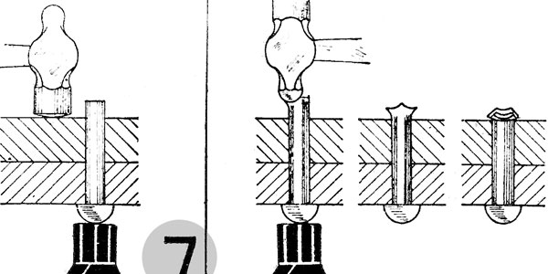
The successive stages in forming the head of the rivet are shown in Figs. 7, 8 and 9. The first step is to be sure the two parts are in proper contact — that is, drawn tightly together after the rivet is inserted in the hole. The sledge or a bucking bar or block is placed against the head of the rivet and the upper part then given a blow with the flat face of the hammer. In forming the head the metal is first “broken down” with the peen of the hammer in successive stages, as shown in Fig. 8, then finished off with the flat of the hammer, as shown in Fig. 9. This operation levels off the irregularities and produces a good looking head.
Another reason for using the flat face of the hammer is that a heavier blow can be delivered to the head which will be transmitted to the body of the rivet where it acts in swelling the metal to the full size of the hole. Light blows and blows with the peen cause only a local flow of metal; they will form a head but will not take care of a poor fit in the hole.
The handiest thing to back up rivets with when heading is an 8-lb. or 12-lb. sledge hammer. If a sledge is not available, any heavy piece of iron or steel may be used, the heavier the better. In some cases it may be necessary to use a round bar and offset the end to gain access to the rivet head. If the parts to be riveted are removable and not too heavy, the heads may be set against a bar of steel held in the vise or on a bench riveting block. The practice of riveting on the vise or on the back of the vise should not be resorted to, as this only indicates carelessness and does not do the vise any good.
If the work must be supported in some manner, as is often the case with hollow parts, use the horn of the anvil providing the work is large enough and the rivet near the end. The heel of the anvil is better adapted for heading rivets than a vise and should have preference when necessary to resort to such method of backing up rivets. When riveting in places where space is limited, it is always well to insert a cold rivet and try the fit of the bucking bar or whatever means are to be used to back up the rivet while heading. It will also be of great help to rehearse completely the operation of heading the rivet to determine what motions and position will be necessary to complete the job in minimum time without interruption.
Another essential to forming a good riveted joint is to have rivets of proper length. The rivets should be cut to length so that the point extends through the holes in which the rivet is to be inserted a distance of one and one-half times the diameter of the rivet. This will allow the correct amount of material to rivet down into a well formed head. The proper heat for the rivet is a cherry reel.
The quickest way to remove a rivet is to use the cold chisel and a heavy hammer. A few blows of the hammer will crack off the head of a rivet up to one-half inch in diameter, and the rest of the rivet can be driven out with a punch. But the quickest way is not always the best way, and that is the case in this instance. In chipping off the head, the blow is resisted by the metal behind the rivet, which is seldom very hard, and the metal is forced out of shape, so that the edge of the hole is elongated. A burr is also raised which must be removed before the new rivet is inserted. To eliminate this difficulty the method shown in Fig. 10 is recommended. In this case a hole is drilled in the head of the rivet of such proportions that it is about 1/32 inch smaller than the diameter of the rivet and to a depth equal to the height of the head or slightly deeper. This reduces the area of the rivet so that a slight blow, one that does no injury to the parts, breaks off the head.
In chipping rivet heads care should be taken to prevent accidents from a flying rivet head, which may cause personal injury or break a window glass if the work is being done indoors. It is good practice to hang up an old coat, sack or similar object so that the rivet head will strike this and thus prevent an accident or other damage.
Small rivets in parts which are removable and in sheet metal which may be removed to the bench or anvil are generally driven in their holes and headed cold. In such cases the riveted joint is accessible enough so that the rivet can be filed or fitted to the hole, or the hole drilled to the size of the rivet, and in making that fit one of the two requirements of good riveting is attained.
The riveting of sheet metal work or work such as might be done by tinners is done along slightly different lines than outlined above. On the farm it would apply to repairs on the spouting and roof drainage of buildings and housings and covers of the various parts of equipment. In this case the holes are generally punched out instead of drilled, and in punching the surface becomes slightly irregular. To get a good joint it is first necessary to remove this irregularity, which may be done with a tinner’s rivet set or by hammering. The point to bear in mind is that the surfaces must be flat if the rivet is to pull up tight. A tinner’s rivet set, while it may be purchased, can also be conveniently made in the farm shop along the lines shown in Fig. 11. Round or square stock may be used. At one end or side of the face a flat or half-round depression is made with a countersink just deep enough to allow for forming the head. At the opposite side a hole is drilled just large enough to provide clearance over the pin or stem of the rivet. This hole is drilled to a depth of about 5/8 inch and another hole is drilled at right angles to this which may be used for drawing the rivet through the metal. When the holes are punched the rivet is inserted and the set placed over the rivet, as shown at “A.” This serves to draw the two parts together, when a blow is delivered to the set with a hammer. The rivet being properly set with head drawn snug on lower part, the stem is given several blows with the hammer and the head finished with the set, as shown at “B.”
When accuracy in alignment of parts is of minor consideration, the rivet set may also be used to draw the rivet, in which case punching of the holes is eliminated. In this operation the rivet is placed on the anvil or riveting block and the metal is placed over the rivet in the correct position. To locate the rivet, strike the metal just above the rivet a sharp blow with a wooden mallet. This will cause the metal to be raised just above the rivet, indicating its location. The hole on the side face of the rivet set is placed directly over the raised portion of the metal and the set is then driven down with the hammer. This will seat the metal around the rivet and leave it projecting through the surface. This operation is repeated, placing the second sheet in position and drawing the rivet through and then heading over as previously described. This method is known as drawing the rivet through, and when the sheets are not too heavy the rivet may be drawn through both at the same time providing they have been clamped together so that their intended relation will be maintained. On tin and very light sheet metal work it saves considerable time, since the operation of punching the holes is eliminated.